Chapter 1, sections 2 and 3 of User's Guide for CPO2D and CPO3D
(or proceed to section 4)
1.2 Outline of the Boundary Element Method
The present program uses the Boundary Element Method (BEM) to find electrostatic potentials and fields for systems of conducting electrodes. CPO2D is designed to deal with systems that have axial or planar symmetry, and CPO3D will deal with systems of more general symmetry, or no symmetry at all! In both cases use can be made of any planes of reflection symmetry that might exist.
The Boundary Element Method is sometimes referred to as the Surface Charge Method or the Integral Equation Method. In our first publications in the 1970's we called the method the Charge Density Method, which has been used by many later authors, but now we prefer the generic description Boundary Element Method.
For a recent description see the publication: Achieving the highest accuracy with the BEM, by F. H. Read, Microscopy and Microanalysis 21 Suppl S4, 182-187 (2015).
The first group to use the Boundary Element Method to obtain systematic lens data was the Manchester group, in the early 1970's -see for example
Electrostatic Cylinder Lenses I: Two element lenses, by F H Read, A Adams and J R Soto-Montiel, J.Phys.E (Sci.Instrum.) 4, 625-32 (1971),
and the 'standard' data book
Electrostatic Lenses, by E Harting and F H Read, Elsevier Publishing Company, Amsterdam (1976).
Copies of the text (non-data) pages of this book are available in the ‘document’ folder of the CPO package.
The principle of the Boundary Element Method is simple. The method is based on the fact that in a system of conducting electrodes, real free charges appear on the surfaces of the electrodes when potentials are applied to them. In the absence of leakages, these charges will remain when the leads that have carried the applied voltages are removed. These surface charges are then the sources of all the potentials and fields in the system. In the Boundary Element Method the electrodes are effectively replaced by these charges.
Consider for example an isolated conducting sphere of radius R. If it has a potential V then its total charge is
q = 4πε0RV
This is uniformly distributed on the surface of the sphere, as illustrated in the figure:
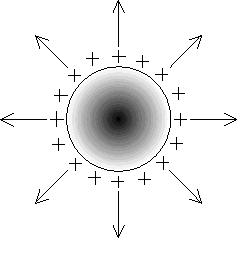
The external potential V and radial field E at a distance r from the centre of the sphere are
V(r) = q/4πε0r E(r) = -q/4πε0r2
The inside of the sphere is field-free. These potentials and fields are due to the surface charges on the sphere. If the sphere could be removed without disturbing the surface charges then the potentials and fields would remain unchanged.
As stated above, the surface charges are the sources of all the potentials and fields in any electrostatic system. In a physical system the surface charges arrange themselves to reproduce the applied potentials and to make the interiors of conducting electrodes field-free. If all the surface charges are known then the all the potentials and fields are also known. In the BEM the surface charges are deduced from the potentials applied to a set of electrode.
The only parts of the system that the user has to model are the surfaces of the electrodes. It is not necessary to create an artificial mesh of points in the space enclosed by the electrodes (as is needed in the Finite Difference and Finite Element Methods) and so there is no need for mesh generation programs.
The system can be unbounded -it is not necessary to enclose it.
There are no restraints on the relative sizes of the electrodes
Cathodes can be of almost any shape and are easy to deal with. The current from a cathode segment is proportional to the area of the segment and also depends of course on the field at the segment.
It is important to note that because the system can be unbound there is no need to include electrodes and surfaces that cannot be 'seen' when dealing with a beam or trapped particles. Such extra electrodes have no effect on the electron optics of the system and should be removed. This is explained in a separate note.
Please note because the BEM method is based on surface charges, that the term 'electrode' is often used in our literature to refer to the surface of an electrode, rather than the whole physical entity.
1.3 Basic segments
In the present programs the surfaces are subdivided into basic segments. Examples of these are the circular hoops into which a cylinder is subdivided in CPO2D, the flat triangles for a sphere or cone in CPO3D, and the flat rectangles for a cylinder in CPO3D. Examples are shown in some of the figures in the Users Guide, namely figures 1.1 (perspective view of a quadrupole-type system), 1.3 (schematic of a double cylinder lens), 1.5 (a sphere automatically subdivided into triangles) and several others.
See also text-books on electron optics.
(proceed to section 1.4)