Charged-particle ray trace Decorative artwork in the style of a CPO simulation plot: charged-particle trajectories, drawn as fine lines, converge through a crossover at a focal point marked by a glowing dot — the kind of ray trace the CPO programs produce.

Capabilities · Examples

Electron optics simulation examples

A gallery of simulations taken directly from the example, benchmark-test and shape files supplied with every CPO licence — from photomultipliers and Pierce guns to quadrupole mass filters and field-emission arrays.

WORKED EXAMPLES

Every picture below is produced directly from a data file supplied with the CPO package. See the full list of example data files, or download the free demo and run them yourself.

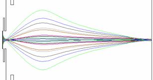
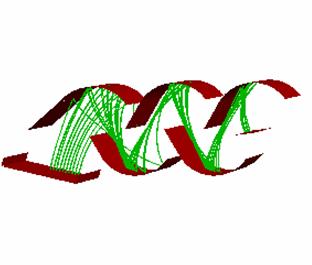
Simulated photomultiplier: electron trajectories cascading between dynodes, multiplying at each impact
CPO3D · example file 48

Photomultiplier

A series of rays start from a line on the photocathode. When a ray hits a dynode its energy is reduced to that of a secondary electron and its current is multiplied by a factor of 3 (as chosen by the user). The initial energies and directions of the secondaries are also chosen by the user and can be randomised.
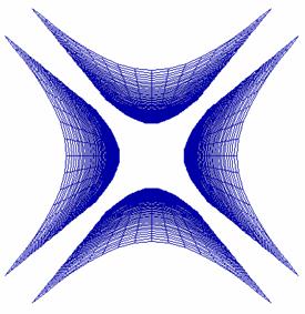
Perspective view of a quadrupole mass filter with four hyperbolic electrodes
CPO3D · example file 5

Quadrupole mass filter

Perspective view. The hyperbolic electrodes are generated from the user’s own equations. Many other non-standard shapes can be generated simply by entering your own equations.

Note that in the Boundary Element Method it is not necessary to enclose the system.

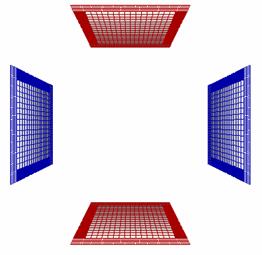
Deflector system of flat rectangular x and y plates, with segment density highest at the plate edges
CPO3D · example file 27

Simple deflector system

Here the x and y deflector plates are flat rectangles. Note that the density of segments is highest at the edges, where the charge density is highest. 12 other types of more sophisticated deflector systems are included as examples in the CPO package.

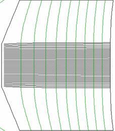
Pierce electron gun simulation with potential contours perpendicular to the space-charge-limited beam
CPO2D · example file 12

Pierce gun

The ray tracing is automatically iterated several times until the results converge. A damping factor is provided which is controlled by the user. Some potential contours are also shown. Note that the combined effects of the surface charges on the electrodes and the space charges in the beam give contours that are perpendicular to the beam, as required for the Pierce gun.

The ‘test’ and ‘example’ files deal with several other types of cathode systems, including thermionic, Schottky and field emission cathodes.

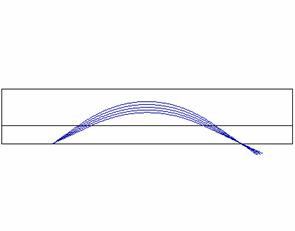
Cylindrical mirror analyzer with five rays brought to a second-order focus at a small spot
CPO3D · benchmark test 16

Ideal CMA (cylindrical mirror analyzer)

Here the 5 rays simulate a beam of full angle 10° and they are allowed to pass through the inner cylinder. The second‑order focusing action of the CMA gives a small spot at the focal point.

Several other ideal and practical energy analyzers are included in the ‘test’ and ‘example’ files.

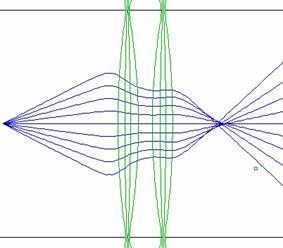
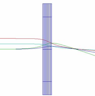
Three-cylinder einzel lens with rays and potential contours, vertical scale expanded
CPO2D · example file 36

3-cylinder einzel lens

The vertical scale has been expanded in this picture and some potential contours are shown. Examples of several other lenses are included in the CPO package.

The programs can automatically vary one or more lens voltages to produce the smallest spot at some defined position (or even to produce a series of spots at different positions, for example for different energies). The program also gives accurate third‑order lens parameters derived from paraxial integrations.

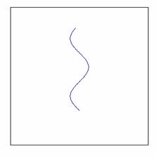
Trajectory of a charged particle in sinusoidal motion in a sinusoidal time-varying field
CPO2D · benchmark test 8

Time-varying fields

Here there is sinusoidal motion in a sinusoidal field.

There are also options for ‘top‑hat’ and ‘saw‑tooth’ time dependencies. Up to three different time dependencies can be applied simultaneously (for example a sine wave plus two harmonics).

Or the user can define a time dependence via an external program. Examples of these programs are included, together with detailed instructions on how to link them to the main program.

X-ray tube simulation: flat thermionic cathode and 100 kV anode, expanded in the transverse direction
CPO2D · example file 43

X-ray tube

A simple tube with a flat thermionic cathode and an anode at 100kV. This view is expanded in the transverse direction. The iterative ‘automatic focusing’ option is used to find the optimum grid voltage. In each iteration step the space‑charge spreading is automatically established by a separate iterative procedure.

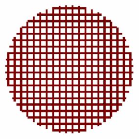
Electrode grid of 289 holes generated from the CPO3D shape library
CPO3D · shape file 19

A grid of 289 holes

One of the library of ready-made electrode shapes that can be scaled, moved, rotated, stretched, cropped, copied and repeated.

Magnetic lens simulation with rays focused by a synthesized magnetic field
CPO3D · example file 46

Magnetic lens

The CPO3D programs can be used to synthesize magnetic fields by superimposing fields from a menu of several different types (for example the fields produced by solenoids, hoops, straight or circular lengths of current, dipoles, etc).

Or the user can generate fields externally on a grid of points and read them in as arrays of pre‑calculated values.

The user can also define a field via an external program which can be easily linked to the main program.

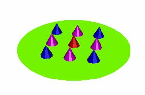
Array of conical nano-tubes simulated as field emission sources
CPO3D · example file 53

Conical nano-tubes as field emission sources

Several other examples deal with carbon nano‑tubes, for example to find the enhancement factors of single tubes or arrays of tubes.

The Surface Charge Method is ideal for dealing with very small structures in the presence of electrodes that are much larger.

expand_less